![[Home]](../iconz/home.gif) Return to Home Page
Return to Home Page
Application Note # C7
CM5/52 -- Reinforced Concrete Pipes
Measurement of cover on reinforced concrete pipes using STANDARD head
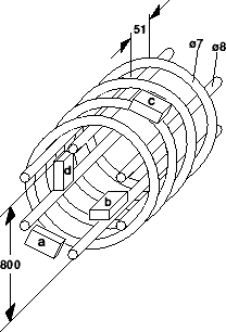
Concrete pipes contain a "cage" of reinforcement (or two concentric ones in the largest sizes).
The cage is constructed of (typically 6) longitudinal bars, and a continuous spiral, welded together.
Figure 1 shows an example (but the curved bars have been drawn as separate rings).
There are four main differences between the measurement of cover in this situation, and the usual measurement of straight bars under a flat surface:
(i) the concrete surface is curved;
(ii) the spiral is curved;
(iii) the spiral is of quite close pitch, and equivalent to closely-spaced parallel bars;
(iv) the structure is welded and therefore electrically joined.
There are four distinct measurement positions:
(a) end measurement from the flange face
(b) longitudinal bar from inside
(c) outside measurement to spiral
(d) inside measurement to spiral
|

Figure 1: Reinforcement cage
|
- I) Concrete curvature:
|
| When measuring from the outside of the pipe, the surface is convex, so the face of the cover meter head touches the concrete, and all is well.
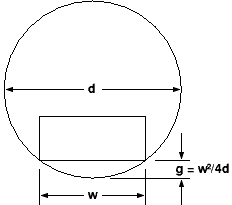
On the inside of the pipe, with a concave surface, the centre of the face of the head is lifted away from the concrete surface: see figure 2.
This positioning error, causing the meter to read too high by the amount of the gap, is given by g = w²/4d. The standard CM5 and CM52 heads are 147mm long by 88mm wide, and the effect of pipe inside diameter is tabulated below:
| 
Figure 2: Offset gap inside
|
        Measuring Longitudinal Bars.   Measuring Spiral Bars
             Pipe i.d.       gap         Pipe i.d.      gap
                480           4             540         10
                550           3½            600          9
                650           3             675          8
                770           2½            770          7
                970           2             900          6
               1290           1½           1080          5
               1940           1            1350          4
                                           1800          3
                                           2700          2
- In all that follows, it will be assumed that this gap has been allowed for.
- II) Bar curvature.
- It would be expected that the cover meter might measure the distance of the bar as averaged over a length approximately equal to the length of the head.
Therefore outside measurements (convex curvature) should read high and inside measurements (concave) read low.
No such effect is expected on the longitudinal bars.
- III) Spiral pitch.
- When measuring one of several closely-spaced parallel bars, it is to be expected that some signal will also be received from adjacent bars, causing the meter to read low. This effect would be more pronounced at greater depths of cover.
No such effect is expected on the longitudinal bars.
- IV) Welded mesh.
|
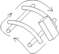
| The CoverMasters operate by generating a pulsed magnetic field parallel to the bars being measured, which induces an electrical current to flow round the circumference of the bar cross-section. When pairs of crossed bars are welded together, they form a continuous rectangular path around which currents can also flow. This generates an additional received signal which can be comparable to that expected from a single bar (see figure 3). This effect turns out to be more important than the mere curvature of the spiral bars.
| 
Figure 3: Eddy-current path around welded mesh
|
![[^Top^]](../iconz/top.gif) Go to top of this page
Go to top of this page
Results of experimental measurements
The cage investigated was of 800mm diameter, the six longitudinal bars being 8mm diameter, and the spiral of 7.3mm diameter bar wound on a 51mm pitch (figure 1).
Measurements were made using a CM5 over black-face covers of 30 to 60mm (which are also equivalent to white-face covers of 0 to 30mm). The longitudinal bars were measured with the DIAM knob set to 8, and the spiral bars at 7. Some measurements were also taken on a piece of spiral removed from the cage in order to isolate effect (II).
- A) End measurement (from flange face of pipe); see figure 1a.
- The concrete surface is flat, so (i) does not apply.
The bar curvature is in the plane of the head, neither convex nor concave, so effect (ii) is negligible.
Due to the relative position of the head and cage, effects (iii) and (iv) are at their least.
The result observed was that the CM5 read consistently 1 (±½)mm low.
- B) Longitudinal bar measurement (inside); see figure 1b.
- There is concave concrete curvature (i), and a small correction (eg 2½mm) was made.
The bar is straight, so (ii) does not apply.
The bars are well spaced, so (iii) does not apply.
Effect (iv) is significant, so a signal is received everywhere, with a very distinct maximum signal (minimum depth indication) when the head is over the bar.
The result observed was that the CM5 read low by 12½% (±1%) of actual distance (14% of indicated cover).
- C) Spiral bar measurement (outside); see figure 1c.
- Concrete curvature is convex, so (i) does not apply.
Convex bar curvature exists, so effect (ii) is expected.
There are adjacent bars, so effect (iii) is expected.
Effect (iv) is significant, and strongest when the head is also over a longitudinal bar. Measurements must be made with the head located midway between longitudinal bars (whose positions will be known from (B) above).
The result from curvature (ii) alone was small: reading consistently 2 (±½)mm high.
The effect of (iii) and (iv) was to introduce an additional error, reading low by 9½% (±1½%) of actual cover.
- D) Spiral bar measurement (inside); see figure 1d.
- Concrete curvature is concave, and a significant correction (eg 7mm) is required.
Concave bar curvature exists, so effect (ii) is expected.
There are adjacent bars, so effect (iii) is expected.
Effect (iv) is significant, and strongest when the head is also over a longitudinal bar. Measurements must be made with the head located midway between longitudinal bars (whose positions will be known from (B) above).
The result from curvature (ii) alone was small: reading consistently 2½ (±½)mm low.
The effect of (iii) and (iv) was to introduce an additional error, reading low by about 9% (±2%) of actual cover; when compounded with (ii) this results in an overall effect of reading low by 14% (±1%) of actual cover (ie one-sixth of indicated cover).
Conclusion.
The effect of curvature is small (a few mm) and easily corrected.
The effect of the welded mesh structure is much greater ( ~10%), but a consistent means of correction can be derived from a small number of calibration measurements.
Using correction tables or formulæ, an absolute measurement can be made to ±1mm or less with the CM5 and CM52.
In situations where a large number of pipes need to be checked for a nominal or minimum cover, the correction(s) necessary need only be determined for that critical value, and the CM5 and CM52 can be relied upon to indicate deviations from that value.
Footnote.
Experiments were also made on the cage with the DIAM knob set to values other than the actual bar diameter. It was found empirically that the CM5 would display true cover directly (apart from the effect of concrete concavity) to an absolute accuracy of ±2mm worst case, ±1mm typical, if:
DIAM is set to 12 when measuring (7mm) spiral bars from outside;
DIAM is set to 8 when measuring (7mm) spiral bars from inside;
DIAM is set to 12 or 16 when measuring (8mm) longitudinal bars from inside (or, better still, an average is used of the readings on 12 and 16).
Although this is "cheating", it does mean that after testing and calibrating on a particular pipe or cage, it is only necessary to keep a record of the DIAM settings to be used for any particular measurement, and the CM5 can then be direct-reading without any further reference to calibration graphs or tables.
![[^Top^]](../iconz/top.gif) Go to top of this page
Go to top of this page
The new midget head now available shows a substantial reduction in errors due to to bar curvature, proximity and the welded-mesh effect, and is described below.
Using the CM5/52 MIDGET Head on pipe reinforcement cages.
The four considerations described earlier still apply;
(i) the concrete surface is curved
(ii) the spiral bars are curved
(iii) the spiral is of close pitch, and
(iv) the structure is welded and therefore electrically continuous.
However reducing the size of the head (from 147 × 88mm to 74 × 49mm) reduces the magnitude of
these effects, as follows:
- I) Concrete curvature:
- the gap between the concrete and the centre of the head when placed inside the pipe now becomes:
        Measuring Longitudinal Bars.   Measuring Spiral Bars
              Pipe i.d.      gap           Pipe i.d.    gap
                  400         1½               460       3
                  600         1                680       2
                 1200          ½              1370       1
- ie about 3 or 4 times smaller than the large-head figures.
- II) Bar curvature:
- the typical effect using the large head was about plus or minus 2mm (according to the measurement being external or internal). Using the small head, this error reduces to ±1mm or less, and therefore becomes negligible.
- III) Spiral Pitch:
- to minimise the effect of adjacent bars, the pitch should be significantly greater than the cover, and also greater than the effective width of the head.
This condition is achieved much more successfully with the small head than with the large head, resulting in an error of typically not more than -1mm. The individual bars are also much more clearly resolved using the small head.
- IV) Welded Mesh:
- this phenomenon is always present. The effect is greatest when the head is also over a transverse bar and least when the head is well clear of transverse bars. With the large head, the biggest problem was when measuring the longitudinal bars, as there would always be some spiral bars under the head; with the small head, this effect is still present, but the magnitude is only -1 or -2mm.
Therefore the overall results of the different measurement positions using the small head
(after allowing for effect (i), the gap) become:
- A) End Measurement:
- no significant error.
- B) Longitudinal Measurement Inside
- (where the longitudinal bar is nearer to the concrete surface than the spiral bars):
- effect (iv) is dominant, giving an error typically -1 to -2mm.
- C) Spiral Measurement Outside:
- effects (ii) and (iii) are both small and in opposite directions so tend to cancel out, and
effect (iv) can be made negligible by positioning the head well away from the longitudinals;
there is no significant resulting error (± 1mm).
- D) Spiral Measurement Inside:
- effects (ii) and (iii) now add together, so with correct positioning to minimise effect (iv), the net resulting error is typically -1 to -1½mm.
As in the case of the Application Note using the large head, when checking a number of nominally identical pipes, it may be helpful to set the DIAM knob to one or two sizes larger than the actual diameter when making inside measurements, the actual adjustment being determined by the user on a known cage structure.
![[^Top^]](../iconz/top.gif) Go to top of this page
Go to top of this page
CoverMaster CM9 covermeter
All the general principles already described are applicable.
The standard search head of the CM9 has dimensions intermediate between those of the Standard and Midget heads of the CM5/52.
The gap-correction table for use when measuring from inside the pipe now becomes:
    Measuring Longitudinal Bars.   Measuring Spiral Bars
          Pipe i.d.      gap           Pipe i.d.    gap
              400         2½               500       8
              500         2                575       7
              660         1½               670       6
             1000         1                800       5
             2000          ½              1000       4
                                          1340       3
                                          2000       2
(The CM9's optional large head would not normally be used inside pipes, and so is not described)
![[Home]](../iconz/home.gif) Return to Home Page . . . . . .
Back to "Technical Library" page
Return to Home Page . . . . . .
Back to "Technical Library" page


![]() Return to Home Page . . . . . .
Back to "Technical Library" page
Return to Home Page . . . . . .
Back to "Technical Library" page